| Line 84: | Line 84: | ||
== Screen Blend Mode == | == Screen Blend Mode == | ||
| − | On top of the default additive blend mode, the people at video copilot also used a mode quite familiar to Adobe products (but not so much to realtime graphics programmers) called the '''screen''' mode. I'll talk a bit about how to achieve this mode using our standard blending pipeline in graphic APIs as it's not that easy ! | + | On top of the default additive blend mode, the people at video copilot also used a mode quite familiar to Adobe products users (but not so much to realtime graphics programmers) called the '''screen''' mode. I'll talk a bit about how to achieve this mode using our standard blending pipeline in graphic APIs as it's not that easy ! |
The screen mode is considered to be the opposite of the multiply mode. The blending equation is like this : | The screen mode is considered to be the opposite of the multiply mode. The blending equation is like this : | ||
| Line 110: | Line 110: | ||
Assuming you patch your shader to return 1-Src instead of Src, you can yet manage to do '''(1-Src)*(1-Dst)''' which is starting to get close enough. | Assuming you patch your shader to return 1-Src instead of Src, you can yet manage to do '''(1-Src)*(1-Dst)''' which is starting to get close enough. | ||
| − | Let's see what happens if we use the reduced screen mode formula '''Dst'=(1-Src)*(1-Dst)''' for 2 | + | Let's see what happens if we use the reduced screen mode formula '''Dst'=(1-Src)*(1-Dst)''' for 2 steps : |
Dst_1 = (1-Src_0)*(1-Dst_0) <== Here, Dst_0 is the original black background | Dst_1 = (1-Src_0)*(1-Dst_0) <== Here, Dst_0 is the original black background | ||
| Line 146: | Line 146: | ||
After spending almost a whole month replicating the Optical Flares technology, I have to admit these guys are quite clever ! They use some pretty cool combinations of additive geometries to achieve nice and unexpected results. | After spending almost a whole month replicating the Optical Flares technology, I have to admit these guys are quite clever ! They use some pretty cool combinations of additive geometries to achieve nice and unexpected results. | ||
| − | That was quite hard work but I'm pretty happy with the result, even though there are some configurations that are still quite wrong and although I couldn't achieve to replicate all their objects faithfully. That's also one of the reasons why I believe the guys at Video Copilot are | + | That was quite hard work but I'm pretty happy with the result, even though there are some configurations that are still quite wrong and although I couldn't achieve to replicate all their objects faithfully. That's also one of the reasons why I believe the guys at Video Copilot are clever (except on their file format), as they have used some pretty messed up functions that I couldn't exactly pinpoint ! |
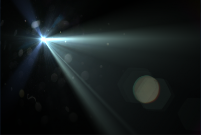
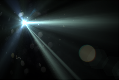
Here is a comparison of the rendering done by Nuaj' and the one in After Effect : | Here is a comparison of the rendering done by Nuaj' and the one in After Effect : | ||
| − | [[File:LensFlareComparisonVC.png|thumb| | + | [[File:LensFlareComparisonVC.png|thumb|center|400px|Video Copilot's Rendering]] [[File:LensFlareComparisonNuaj'.png|thumb|center|400px|Nuaj' Rendering]] |
| + | |||
There are obvious discrepancies like luminosity levels, difference in sharpness of some elements and obviously the randomly placed elements not being at the exact same place in both renderings. Some of these are due to simplifications on my parts, others to inaccurate formulas and as there can be up to 20 elements, each may be displaying hundreds of additive primitives, the differences can show pretty rapidly but I believe they are quite acceptable for my purpose. | There are obvious discrepancies like luminosity levels, difference in sharpness of some elements and obviously the randomly placed elements not being at the exact same place in both renderings. Some of these are due to simplifications on my parts, others to inaccurate formulas and as there can be up to 20 elements, each may be displaying hundreds of additive primitives, the differences can show pretty rapidly but I believe they are quite acceptable for my purpose. | ||
Revision as of 00:35, 19 June 2011
Contents
[hide]Post-Processing : Lens Flares
Lens flares are common post-processes that were rendered popular by the infamous "Lens Flare" filter in Photoshop which can be easily recognized in many synthetic images from the early 90s (and still today in images from suspicious websites as it's quite official that this plug-in, although serving its purpose in its time, is now a proof of arguable taste).
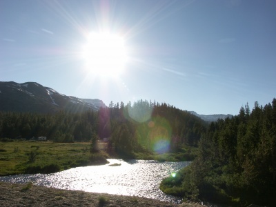
Lens flares are created by light entering through a camera objective and reflecting multiple times off the surface of the numerous lenses inside it, creating several recognizable artifacts.
I won't linger on the optical details of what creates which lens-flare artifact, I'm only concentrating on their visual aspect. For that purpose, I relied on a well known After Effects plug-in called "Optical Flares" by Video Copilot (http://www.videocopilot.net/products/opticalflares/).
Before reading any further, I advise you to watch the nice tutorial video of this plug-in so you get familiar with its capabilities and vocabulary.
The Lens Flare Class
I attached myself to the annoying task of reverse engineering the OFP / Optical Flares Preset file format.
For details on the file format, check the Video Copilot "Optical Flares" File Format page.
The LensFlare class is written in C# and is available here : http://www.patapom.com/Temp/LensFlare.cs
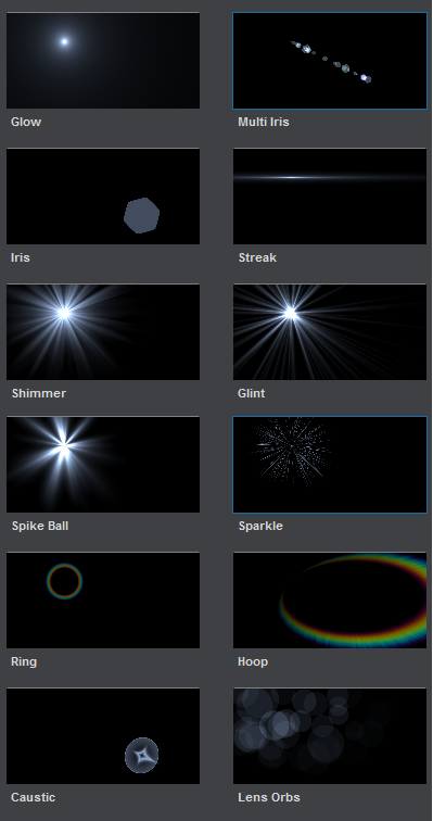
It reflects all the informations contained in an OFP file and supports the 12 kinds of Lens Objects that exist in Optical Flares, shown in the image below.
Of course, this class only describes a lens flare, it doesn't display a lens-flare. So that's what we're going to see later.
Global Modifiers
All lens objects have these parameters in common :
- Brightness, the overall brightness of the effect
- Transform, these parameters combine the position, rotation, scale and offsetting to position the object on screen properly
- Colorize, these parameters allow to use either the global flare color, a single custom color, a gradient or a "spectrum" gradient showing all the colors of the rainbow. All gradients can be offset or wrap multiple times.
- Dynamic Triggering, these parameters control how the trigger can be positioned and activated depending on where the light or object stands on the screen. This allows to modify key parameters of the object based on its position. For example, make an object get brighter when standing in the dead center of the screen, or streaks getting larger when they reach the screen's border.
- Circular Completion, (not available on all objects) this allows to "cut" the effect based on the angle of a point with the effect's center. You can use this to create incomplete rings or irises.
Local Parameters
On top of these global parameters, each lens object has different local parameters like its complexity, its length, thickness, spacing and random variations on these parameters.
Some of the objects (the ones with random length/brightness/thickness) also have a simple animation of their brightness and length by specifying an animation amount and speed.
Displaying
All objects in the Lens Flare render technique use a single empty point that is instanced as many times as there are entities in the object.
Quad objects
Some object are displayed using a single quad entity where the pixel shader does all the work of clipping and computing the correct color for each pixel. That is the case for :
- Hoops
- Rings
- Sparkles
- Glow
Special Geometries
All other objects instantiate their geometry via a geometry shader for each point instance.
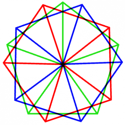
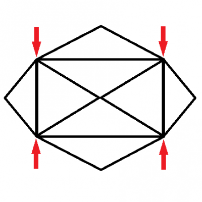
- Shimmer instantiates N fans radiating from the center forming a polygon. That one was really tricky to replicate as they actually add 3 polygons together, the amount of angles of the polygons being dictated by the shimmer's complexity parameter.
- Glint instantiates N narrow triangles radiating from the center like spikes.
- Streaks instantiate a very strange primitive, like a very wide rectangle with internal vertices that can collapse toward the horizontal line to narrow the streak down.
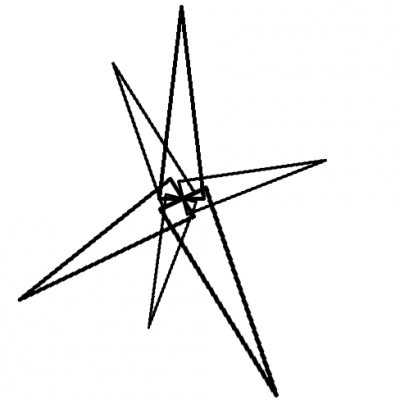
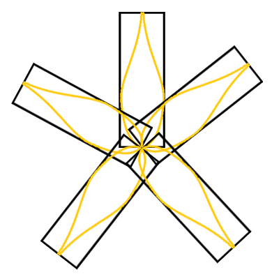
- Spike balls instantiates N petals-shaped narrow rectangles.
- Iris instantiate N quads where is drawn a procedural shape (circle or polygon). Irises can also apply textures from a bank instead of a procedural generation. Irises are the most common and recognizable objects in lens-flares.
Screen Blend Mode
On top of the default additive blend mode, the people at video copilot also used a mode quite familiar to Adobe products users (but not so much to realtime graphics programmers) called the screen mode. I'll talk a bit about how to achieve this mode using our standard blending pipeline in graphic APIs as it's not that easy !
The screen mode is considered to be the opposite of the multiply mode. The blending equation is like this :
Dst' = 1-(1-Src)*(1-Dst)
or
Dst' = Src + Dst - Src*Dst
For the sake of completeness, let's recall what our familiar blending pipeline is able to perform :
Dst' = Src * SrcParam (OP) Dst * DstParam
where :
- Src is the pixel you're writing in the shader
- Dst is the pixel previously written on screen that we'll blend with
- (OP) is the blend operation which is either ADD, SUB, REV_SUB, MIN or MAX
- SrcParam and DstParam can be many things like 1, 0, Src, Dst, 1-Src, 1-Dst or alpha
We can see it's easy to do Src*(1-Dst) or Dst*(1-Src) but no way we can do the complex screen mode...
So, how can we achieve the correct function ?
Assuming you patch your shader to return 1-Src instead of Src, you can yet manage to do (1-Src)*(1-Dst) which is starting to get close enough.
Let's see what happens if we use the reduced screen mode formula Dst'=(1-Src)*(1-Dst) for 2 steps :
Dst_1 = (1-Src_0)*(1-Dst_0)   <== Here, Dst_0 is the original black background
Dst_2 = (1-Src_1)*(1-Dst_1) = (1-Src_1)*( 1-(1-Src_0)*(1-Dst_0) )
If Dst_1 would have been the exact screen mode, we would have CorrectDst_1=1-(1-Src_0)*(1-Dst_0) instead of WrongDst_1=(1-Src_0)*(1-Dst_0) then Dst_2 would really have been :
Dst2 = (1-Src_1)*(1-CorrectDst_1) = (1-Src_1)*(1-(1-(1-Src_0)*(1-Dst_0))) = (1-Src_1)*((1-Src_0)*(1-Dst_0)) = (1-Src_1)*WrongDst_1
So we see that using a wrong we make a right ! It means that using the (1-Src)*Dst blending operation is actually performing the right operation on the second step ! Recursively, Dst_2 is also wrong as Dst_1 before it because it's not complemented, but re-applying
Dst_3 = (1-Src_3)*Dst_2
will actually complement Dst_2 in that stage. So we can deduce that, except for the first stage and the last (that will need to be complemented manually), all intermediate stages will do alright if we use the (1-Src)*Dst blend operation !
To sum up, to obtain a correct screen mode, all we need to do is :
- Dst_0' = 1 - Dst_0 <-- First complement of the original background
- N passes of rendering using the Dst_i+1 = (1-Src_i)*Dst_i blend mode
- A final complement of the last Dst_N buffer
So here you go : screen blend mode for you
It may not look like much but the difference between screen and additive blend modes is actually quite important as shown in the examples below :
Post-Mortem
After spending almost a whole month replicating the Optical Flares technology, I have to admit these guys are quite clever ! They use some pretty cool combinations of additive geometries to achieve nice and unexpected results.
That was quite hard work but I'm pretty happy with the result, even though there are some configurations that are still quite wrong and although I couldn't achieve to replicate all their objects faithfully. That's also one of the reasons why I believe the guys at Video Copilot are clever (except on their file format), as they have used some pretty messed up functions that I couldn't exactly pinpoint !
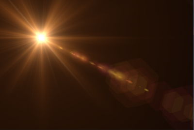
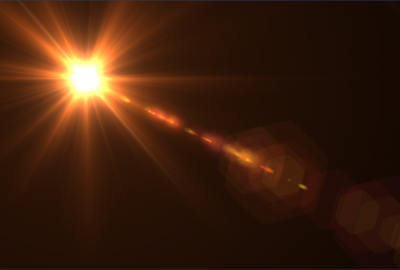
Here is a comparison of the rendering done by Nuaj' and the one in After Effect :
There are obvious discrepancies like luminosity levels, difference in sharpness of some elements and obviously the randomly placed elements not being at the exact same place in both renderings. Some of these are due to simplifications on my parts, others to inaccurate formulas and as there can be up to 20 elements, each may be displaying hundreds of additive primitives, the differences can show pretty rapidly but I believe they are quite acceptable for my purpose.
