Contents
[hide]Color Spaces
A color space is the 3-dimensional space in which colors can be represented. 3 dimensions are enough for most applications to describe a color faithfully but various conventions can be chosen to create each dimension depending on the intended goal (processing, display, accuracy, perception, etc.).
Some of the color spaces are RGB, CIEXYZ, CIExyY, CIELAB, HSV, HSB, HSL, YUV.
RGB
Color Management
A color managed system comprises three basic components, namely: -
- A device-independent color space - this is usually referred to as the Working or Reference color space.
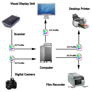
- ICC profiles for each device (i.e. printer, scanner, monitor, digital camera, etc.) that will accurately describe the unique color characteristics of each device.
- A Color Matching Module (CMM) that will interpret the information contained within the device profiles and carry out the instructions on how the color characteristics of each device should be treated.
Color Profile
(source: http://www.computer-darkroom.com/ps10_colour/ps10_1.htm)
A digital image will usually comprise many millions pixels, each of which is represented by a numeric value. The value assigned to each pixel will describe many attributes but in this essay it's the color value or mix (e.g. RGB value) that we're most interested in. As I have already mentioned, when a color is device-dependent, the appearance of pixels with identical values will very often differ because each device has its own unique way of translating the color "value" or "number" into visual color. The role of ICC profiles is to ensure that discrepancies that result from the widely differing color characteristics of each device are known to the color management system. If we were discussing spoken language rather than color, then the ICC profile would be synonymous with a translator.
Device profiles come in two basic forms, i.e. Input and Output.
- Input profiles typically describe the color characteristics of scanners and digital cameras
- Output profiles describe devices such as monitors, printers and film recorders.
Input profiles are often referred to as one-way since they represent the source device. For obvious reasons we can never convert a document into the color space of our scanner or digital camera. Output profiles on the other hand are two-way meaning we can convert From or To them. For example, we can convert a document with an embedded monitor profile into a document that has a color profile describing a printer, or vice versa.
Consumer class film and flatbed scanner applications have been ICC aware for some time now, with the vendors usually choosing sRGB as their preferred color space, which is a bit of a misnomer because sRGB is not a device color space. Clearly, these vendors are doing some work behind the scenes so as to keep things simple for the user, which isn't necessarily as wise as it might first appear. The sRGB color space isn't generally regarded as appropriate for high quality image editing, especially when print or film output is required. So, to overcome this some vendors also provide the user with the option of choosing from a small selection of alternatives. For example, printer vendors such as Epson provide generic ICC profiles with their photo class printers, although it's generally accepted these profiles are rarely as accurate as users would like. Nevertheless, they are getting better with each new generation of printer. As a rule, truly accurate color matching usually requires customized ICC profiles for each device and/or media type. These ICC profiles can be created professionally or you can buy your own profiling application.
ICC Profiles
So, we have Device Profiles and Working Space Profiles - how do they interact?
The first thing we need to understand is that for any color profile to be useful to the color management system, they must conform with the ICC standard. In fact you'll more often see such profiles referred to as just ICC profiles. Anyway, without the aid of device profiles the accurate translation of the document color data (the RGB numbers) from the scanner or digital camera into the Working Space will prove very difficult, if not impossible. Likewise, without the aid of accurate media specific printer profiles, the translation from the Working Space into the color space of a digital printer will prove equally difficult. We also need an accurate monitor profile so as to ensure that what we see on the monitor is a true representation of the document color.
The flow diagram on the right demonstrates a typical imaging workflow, with the document being passed between devices: - from scanner/digital camera - to - computer - to - monitor - and printer.
Black Body
A black body is an idealized physical body that absorbs all incident electromagnetic radiation. Because of this perfect absorptivity at all wavelengths, a black body is also the best possible emitter of thermal radiation, which it radiates incandescently in a characteristic, continuous spectrum that depends on the body's temperature. At Earth-ambient temperatures this emission is in the infrared region of the electromagnetic spectrum and is not visible. The object appears black, since it does not reflect or emit any visible light.
The thermal radiation from a black body is energy converted electrodynamically from the body's pool of internal thermal energy at any temperature greater than absolute zero. It is called blackbody radiation and has a frequency distribution with a characteristic frequency of maximum radiative power that shifts to higher frequencies with increasing temperature. As the temperature increases past a few hundred degrees Celsius, black bodies start to emit visible wavelengths, appearing red, orange, yellow, white, and blue with increasing temperature. When an object is visually white, it is emitting a substantial fraction as ultraviolet radiation.
In terms of wavelength (λ), Planck's law is written:
- <math>B_\lambda(T) =\frac{2 hc^2}{\lambda^5}\frac{1}{ e^{\frac{hc}{\lambda k_\mathrm{B}T}} - 1}</math>
where B is the spectral radiance, T is the absolute temperature of the black body, kB is the Boltzmann constant, h is the Planck constant, and c is the speed of light.
(source http://en.wikipedia.org/wiki/Planck%27s_law)
| Temperature | Source |
|---|---|
| 1,700 K | Match flame |
| 1,850 K | Candle flame, sunset/sunrise |
| 2,700–3,300 K | Incandescent light bulb |
| 3,200 K | Studio lamps, photofloods, etc. |
| 3,350 K | Studio "CP" light |
| 4,100–4,150 K | Moonlight, xenon arc lamp |
| 5,000 K | Horizon daylight |
| 5,500–6,000 K | Vertical daylight, electronic flash |
| 6,500 K | Daylight, overcast |
| 6,500–9,300 K | LCD or CRT screen |
| These temperatures are merely characteristic; considerable variation may be present. | |
CIE Illuminants
Used for :
- Describing general lighting conditions (when taking a picture, or displaying one).
- Spectral characteristics similar to natural light sources
- Reproducible in the laboratory
1931 Illuminants
- Illuminant A = Typical Incandescent Light (2856 K)
- Illuminant B = Direct Sunlight
- Illuminant C = Average daylight from total sky (ambient sky light)
1963 Illuminants
- Illuminant D = Phases of daylight.
- Necessarily followed by the first 2 digits of the CCT (e.g. D65 = D 6504K)
- Represent daylight more completely and accurately than do Illuminants B and C because the spectral distributions for the D Illuminants have been defined across the ultraviolet (UV), visible, and near-infrared (IR) wavelengths (300–830 nm).
- Most industries use D65 when daylight viewing conditions are required
- D50 is used by graphic arts industry => more spectrally balanced across spectrum
Please refer to the D Illuminant Computation page for an interesting way of computing the SPD from CCT.
Other Illuminants
- Illuminant E = Equal energy illuminant
- Illuminant F = Fluorescent lamps of different composition.
- F1–F6 "standard" fluorescent lamps consist of two semi-broadband emissions of antimony and manganese activations in calcium halophosphate phosphor.
- F4 is of particular interest since it was used for calibrating the CIE Color Rendering Index (the CRI formula was chosen such that F4 would have a CRI of 51).
- F7–F9 are "broadband" (full-spectrum light) fluorescent lamps with multiple phosphors, and higher CRIs.
- F10–F12 are narrow triband illuminants consisting of three "narrowband" emissions (caused by ternary compositions of rare-earth phosphors) in the R,G,B regions of the visible spectrum. The phosphor weights can be tuned to achieve the desired CCT.
White Point
(source from http://en.wikipedia.org/wiki/Standard_illuminant#White_point)
The spectrum of a standard illuminant, like any other profile of light, can be converted into tristimulus values. The set of three tristimulus coordinates of an illuminant is called a white point. If the profile is normalised, then the white point can equivalently be expressed as a pair of chromaticity coordinates. If an image is recorded in tristimulus coordinates (or in values which can be converted to and from them), then the white point of the illuminant used gives the maximum value of the tristimulus coordinates that will be recorded at any point in the image, in the absence of fluorescence. It is called the white point of the image. The process of calculating the white point discards a great deal of information about the profile of the illuminant, and so although it is true that for every illuminant the exact white point can be calculated, it is not the case that knowing the white point of an image alone tells you a great deal about the illuminant that was used to record it.
White points of standard illuminants
A list of standardized illuminants, their CIE chromaticity coordinates (x,y) of a perfect reflecting (or transmitting) diffuser, and their correlated color temperatures (CCTs) are given below. The CIE chromaticity coordinates are given for both the 2 degree field of view (1931) and the 10 degree field of view (1964). The color swatches represent the hue of each white point, calculated with luminance Y=0.54 and the standard observer, assuming correct sRGB display calibration.
| Name | CIE 1931 2° | CIE 1964 10° | CCT (K) | Hue | Note | ||
|---|---|---|---|---|---|---|---|
| x2 | y2 | x10 | y10 | ||||
| A | 0.44757 | 0.40745 | 0.45117 | 0.40594 | 2856 | Incandescent / Tungsten | |
| B | 0.34842 | 0.35161 | 0.34980 | 0.35270 | 4874 | {obsolete} Direct sunlight at noon | |
| C | 0.31006 | 0.31616 | 0.31039 | 0.31905 | 6774 | {obsolete} Average / North sky Daylight | |
| D50 | 0.34567 | 0.35850 | 0.34773 | 0.35952 | 5003 | Horizon Light. ICC profile PCS | |
| D55 | 0.33242 | 0.34743 | 0.33411 | 0.34877 | 5503 | Mid-morning / Mid-afternoon Daylight | |
| D65 | 0.31271 | 0.32902 | 0.31382 | 0.33100 | 6504 | Noon Daylight: Television, sRGB color space | |
| D75 | 0.29902 | 0.31485 | 0.29968 | 0.31740 | 7504 | North sky Daylight | |
| E | 1/3 | 1/3 | 1/3 | 1/3 | 5454 | Equal energy | |
| F1 | 0.31310 | 0.33727 | 0.31811 | 0.33559 | 6430 | Daylight Fluorescent | |
| F2 | 0.37208 | 0.37529 | 0.37925 | 0.36733 | 4230 | Cool White Fluorescent | |
| F3 | 0.40910 | 0.39430 | 0.41761 | 0.38324 | 3450 | White Fluorescent | |
| F4 | 0.44018 | 0.40329 | 0.44920 | 0.39074 | 2940 | Warm White Fluorescent | |
| F5 | 0.31379 | 0.34531 | 0.31975 | 0.34246 | 6350 | Daylight Fluorescent | |
| F6 | 0.37790 | 0.38835 | 0.38660 | 0.37847 | 4150 | Lite White Fluorescent | |
| F7 | 0.31292 | 0.32933 | 0.31569 | 0.32960 | 6500 | D65 simulator, Daylight simulator | |
| F8 | 0.34588 | 0.35875 | 0.34902 | 0.35939 | 5000 | D50 simulator, Sylvania F40 Design 50 | |
| F9 | 0.37417 | 0.37281 | 0.37829 | 0.37045 | 4150 | Cool White Deluxe Fluorescent | |
| F10 | 0.34609 | 0.35986 | 0.35090 | 0.35444 | 5000 | Philips TL85, Ultralume 50 | |
| F11 | 0.38052 | 0.37713 | 0.38541 | 0.37123 | 4000 | Philips TL84, Ultralume 40 | |
| F12 | 0.43695 | 0.40441 | 0.44256 | 0.39717 | 3000 | Philips TL83, Ultralume 30 | |
References
An Introduction to Appearance Analysis (2001) http://www.color.org/ss84.pdf


