| Line 112: | Line 112: | ||
return Result; | return Result; | ||
} | } | ||
| + | |||
| + | Which can be viewed like this : | ||
| + | |||
| + | [[File:SHEnvMapCompositing.png]] | ||
See how the W and XYZ component are intertwined ? Each of them are multiplied together using the SH triple product. A good implementation can be found in [http://research.microsoft.com/en-us/um/people/johnsny/papers/shtriple_fixed.pdf Snyder's Paper] that needs "only" 120 multiplications and 74 additions (twice that as we're doing 2 products). | See how the W and XYZ component are intertwined ? Each of them are multiplied together using the SH triple product. A good implementation can be found in [http://research.microsoft.com/en-us/um/people/johnsny/papers/shtriple_fixed.pdf Snyder's Paper] that needs "only" 120 multiplications and 74 additions (twice that as we're doing 2 products). | ||
Revision as of 14:09, 11 January 2011
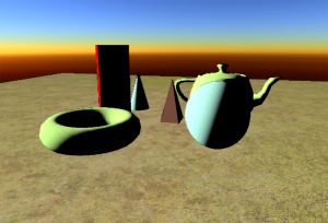
NOTE : The snapshots displayed here are from my deferred rendering pipeline and use the "inferred lighting" technique that renders lights into a downscaled buffer. The upscale operation is still buggy and can show outlines like cartoon rendering but these are in no way related to the technique described here. Hopefully, the problem will be fixed pretty soon... ![]()
Contents
Incentive
Using Nuaj and Cirrus to create test projects is alright, but came a time where I needed to start what I was put on this Earth to do : deferred HDR rendering. So naturally I started writing a deferred rendering pipeline which is quite advanced already. At some point, I needed a sky model so, naturally again, I turned to HDR rendering to visualize the result.
When you start talking HDR, you immediately imply tone mapping. I implemented a version of the "filmic curve" tone mapping discussed by John Hable from Naughty Dog (a more extensive and really interesting talk can be found here [1]) (warning, it's about 50Mb !).
But to properly test your tone mapping, you need a well balanced lighting for your test scene, that means no hyper dark patches in the middle of a hyper bright scene, as is usually the case when you implement directional lighting by the Sun and... no ambient !
Let's put some ambience
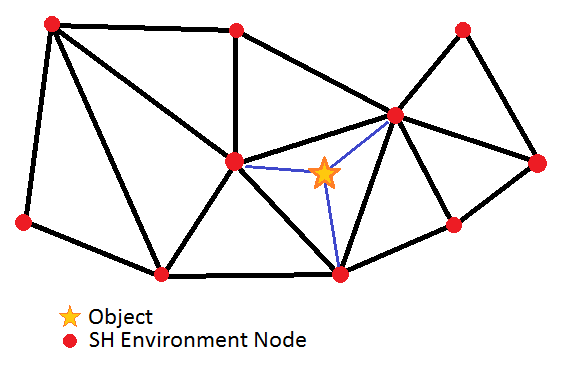
That's when I decided to re-use my old "ambient SH" trick I wrote a few years ago. The idea was to pre-compute some SH for the environment at different places in 2D in the game map, and to evaluate the irradiance for each object depending on its position in the network, as shown in the figure below.
The game map seen from above with the network of SH environment nodes.
The algorithm was something like :
For each object
{
 Find the 3 SH nodes the object stands in
 ObjectSH = Interpolate SH at object's position
 Render( Object, ObjectSH );
}
And the rendering was something like (in shader-like language) :
float3  ObjectSH[9]; // These are the ObjectSH from the previous CPU algorithm and they change for every object

float3   PixelShader() : COLOR
{
 float3 SurfaceNormal = RetrieveSurfaceNormal(); // From normal maps and stuff...
 float3 Color = EstimateIrradiance( SurfaceNormal, ObjectSH ); // Evaluates the irradiance in the given direction
}
The low frequency nature of irradiance allows us to store a really sparse network of nodes and to concentrate them where the irradiance is going to change rapidly, like near occluders or at shadow boundaries. The encoding of the environment in spherical harmonics is simply done by rendering the scene into small cube maps (6x64x64) using each texel's solid angle (the solid angle for a cube map texel can be found here). More on that subject is discussed in the last section.
This was a neat and cheap trick to add some nice directional ambient on my objects. You could also estimate the SH in a given direction to perform some "glossy reflection" or even some translucency using a vector that goes through the surface. That was the end of those ugly normal maps that don't show in shadow !
And all for a very low memory/disk storage as I stored only 9 RGBE packed coefficients (=36 bytes) + a 3D position in the map (=12 bytes) that required 48 bytes per "environment node". The light field was rebuilt when the level was loaded and that was it.
Unfortunately, the technique didn't allow to change the environment in real time so I oriented myself to a precomputed array of environment nodes : the network of environment nodes was rendered at different times of the day, and for different weather conditions (we had a whole skydome and weather system at the time). You then needed to interpolate the nodes from the different networks based on your current condition, and use that interpolated network for your objects in the map.
Another obvious inconvenience of the method is that it's only working in 2D. That was something I didn't care about at the time (and still don't) as a clever mind can always upgrade the algorithm to handle several layers of environments stacked vertically and interpolate between them...
Upgrade
For my deferred rendering though, I really wanted something dynamic and above all, something I would render in screen space as any other light in the deferred lighting stage. I had omni, spots, directionals so why not a fullscreen ambient pass ?
My original idea was neat but I had to compute the SH for every object, and to interpolate them manually. I didn't like the idea to make the objects dependent on lighting again, which would defeat the purpose of deferred lighting.
SH Environment Map
My first idea was to render the environment mesh into a texture viewed from above and let the graphic card interpolate the SH nodes by itself (and it's quite good at it I heard).
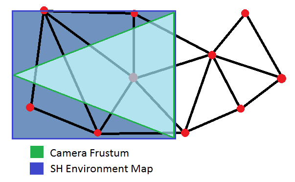
I decided to create a vertex format that took a 3D position, 9 SH coefficients and triangulate my SH environment nodes into a mesh that I would "somehow" render in a texture. I needed to render the pixels the camera can see, so the only portion of the SH environment mesh I needed was some quad that bounded the 2D projection of the camera frustum, as seen in the figure below.
Again, due to the low frequency of the irradiance variation, it's not necessary to render into a texture larger than 256x256.
I also use a smaller frustum for the environment map rendering than the actual camera frustum, to concentrate on object close to the viewer. Another option would be to "2D project" vertices in 1/DistanceToCamera as for conventional 3D object so we maximize resolution for pixels that are closer to the camera but I haven't found the need yet (anyway, I haven't tested the technique on large models either so maybe it will come handy sooner than later !).
What do we render in the SH env map ?
We have the power of the vertex shader to process SH Nodes (that contain a position and 9 SH coefficients as you remember). That's the ideal time to process the SH in some way that allows us to make the environment fully dynamic.
I decided to encode 2 kinds of information in each SH vertex (that are really float4 as you can see below) :
- The indirect diffuse lighting in XYZ
- The direct light occlusion in W
But direct lighting is harsh, it's very high frequency and creates hard shadows. You should never encode direct lighting in SH, unless you have many SH bands and we only have 3 here (i.e. 9 coefficients).
That's why only the direct sky light will be used as direct light source, because it's smooth and varies slowly.
The indirect diffuse lighting, on the other hand, varies slowly, even if lit by a really sharp light like the Sun. That's because it's a diffuse reflection of the Sun, and diffuse reflections are smooth.
We also provide the shader that renders the env map with 9 global SH coefficients, each being a float4 :
- The Sky light in XYZ
- The monochromatic Sun light in W that will be encoded as a cone SH (using only luminance is wrong as the Sun takes a reddish tint at sunset, but it's quite okay for indirect lighting which is a subtle effect)
What we are going to do is basically something like this (sorry for the HLSL-like vertex shader code) :
float4   SHLight[9];   // 9 Global SH Coefficients (XYZ=Sky W=Sun)

float3[]  VertexShader( float4 SHVertex[9] )  // 9 SH Coefficients per vertex (XYZ=IndirectLighting W=DirectOcclusion)
{
  // First, we compute occluded sky light
  float3   SkyLight[9] = { SHLight[0].xyz, SHLight[1].xyz, SHLight[2].xyz, (...) };
  float    Occlusion[9] = { SHVertex[0].w, SHVertex[1].w, SHVertex[2].w, (...) };
  float3   OccludedSkyLight = Product( SkyLight, Occlusion );

  // Second, we compute indirect sun light
  float3   IndirectReflection[9] = { SHVertex[0].xyz, SHVertex[1].xyz, SHVertex[2].xyz, (...) };
  float    SunLight[9] = { SHLight[0].w, SHLight[1].w, SHLight[2].w, (...) };
  float3   IndirectLight = Product( IndirectReflection, SunLight );

  // Finally, we return the sum of both
  float3   Result[9] = { OccludedSkyLight[0] + IndirectLight[0], OccludedSkyLight[1] + IndirectLight[1], (...) };
  return Result;
}
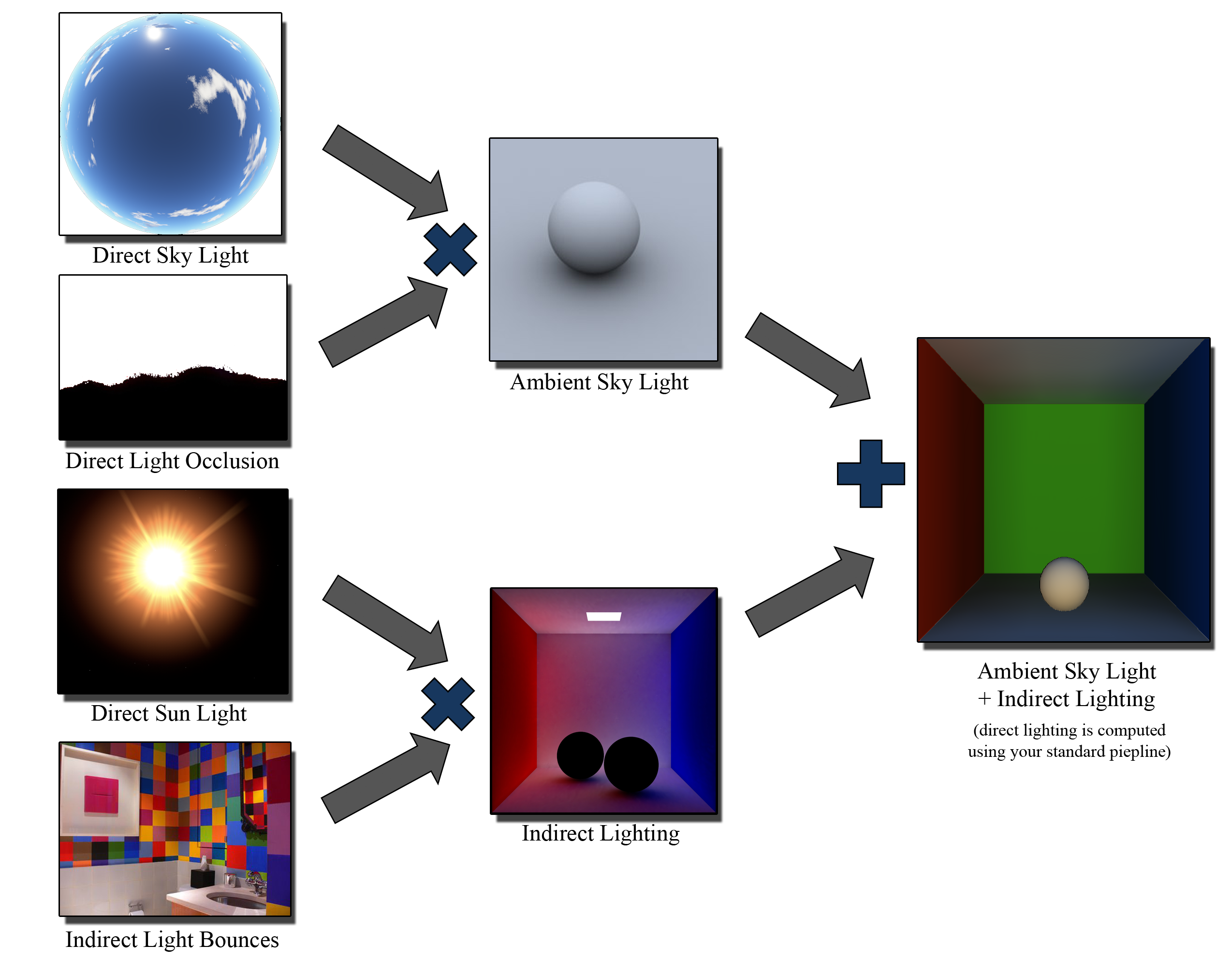
Which can be viewed like this :
See how the W and XYZ component are intertwined ? Each of them are multiplied together using the SH triple product. A good implementation can be found in Snyder's Paper that needs "only" 120 multiplications and 74 additions (twice that as we're doing 2 products).
That may seem a lot but don't forget we're only doing this on vertices of a very sparse environment mesh. The results are later interpolated by the card and each pixel is written "as is" (no further processing is needed in the pixel shader).
Anyway, this is not as easy as it looks : as you may have noticed, we're returning 9 float3 coefficients. You have 2 options here :
- Write each coefficient in a slice of a 3D texture using a geometry shader and the SV_RenderTargetArrayIndex semantic (that's what I did)
- Render into multiple render targets, each one receiving a different coefficient
No matter what you choose though, you'll need at most 7 targets/3D slices since you're writing 9*3=27 SH components that can be packed in 7 RGBA textures (as there is room for 7*4=28 coefficients).
Using the table
So, we obtained a nice 3D texture of 256x256x7 filled with SH coefficients. What do we do with it ?
This part is really simple. We render a screen quad and for every pixel :
- Retrieve the world position and normal from the geometry buffers provided by our deferred renderer
- Use the world position to retrieve the 9 SH coefficients from the SH Env Map calculated earlier
- Estimate the irradiance in the normal direction using the SH coefficients
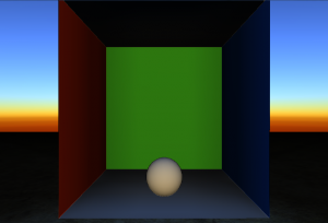
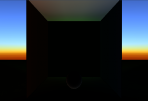
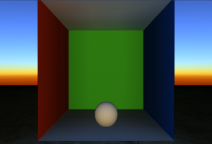
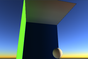
Here are some results in a simplified Cornell box where 16 samples have been taken (a grid of 4x4 samples laid on the floor of the box) :
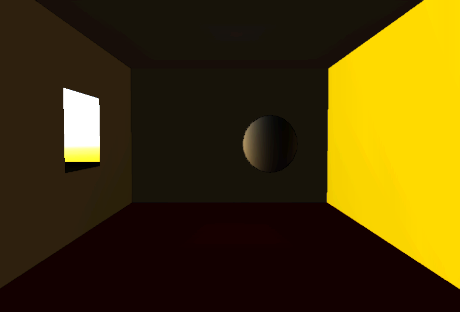
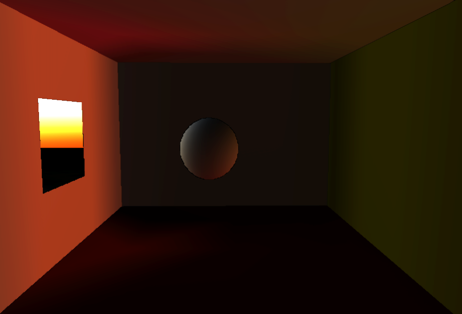
From left to right : (1) Ambient Sky Light Only, (2) Indirect Sun Light Only, (3) Ambient Sky Light + Indirect Sun Light, (4) Ambient + Indirect + Direct Lighting (no shadows at present time, sorry)
Interestingly enough, we can move dynamic objects in the scene and they will be correctly occluded and receive color bleeding from their environment :
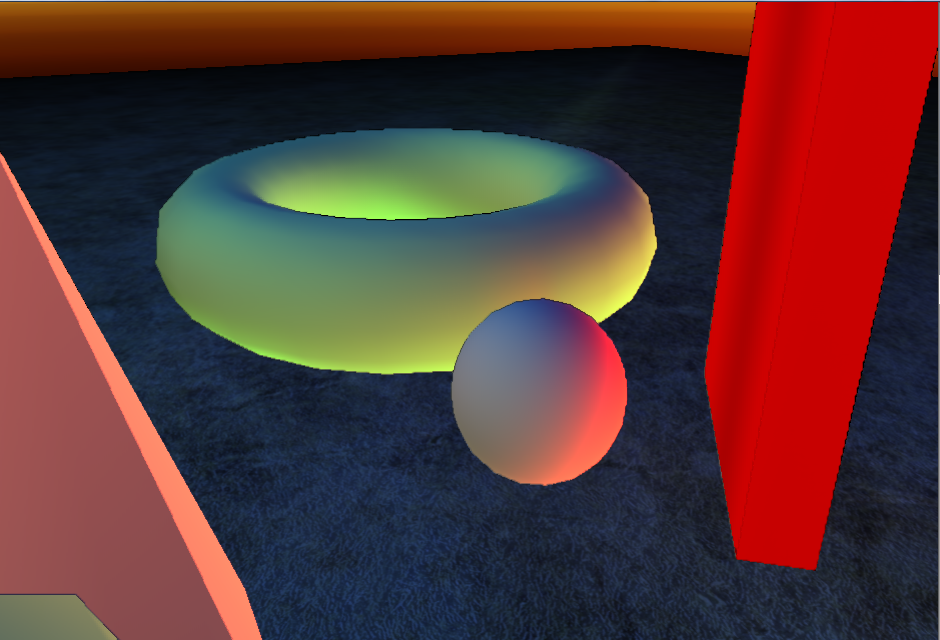
(In this picture, only ambient and indirect lighting is shown and the indirect lighting has been boosted by a factor 3 to emphasize the color bleeding effect)
Another interesting feature is the addition of important light bounces almost for free, as shown in that image where only 1 sample has been dropped in the middle of the room (only ambient and indirect lighting is shown and, without the SH env map technique, the room would be completely dark) :
Here is another shot with 3x3 samples (always 6x64x64 cube maps) :
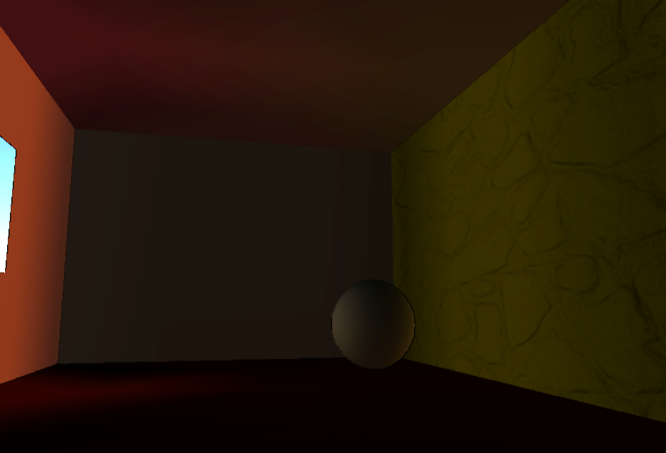
Last but not least, another interesting feature is the revelation of the normals even in shadow. In this image, no lighting other than ambient and indirect is used so the normal map would not show using traditional techniques :
(also notice the yellow bleeding on the dynamic sphere ![]() )
)
Final Result
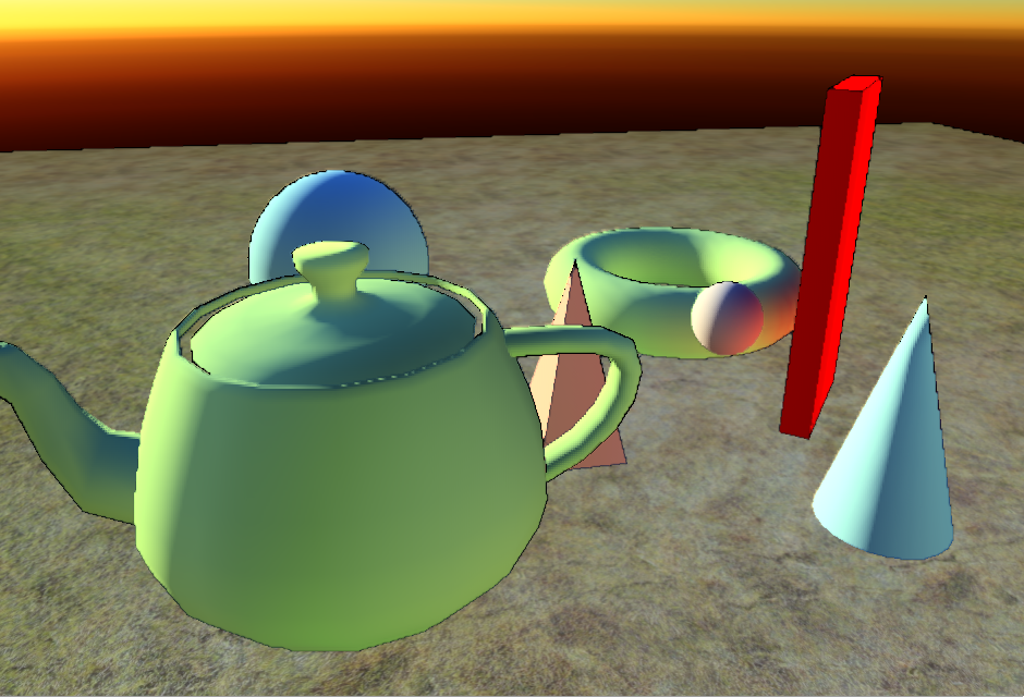
Finally, combining all the previously mentioned features and direct lighting (still lacking shadows, I know), I get a nice result to test my tone mapping ![]() :
:
Pre-Computing the Samples
If your renderer is well conceived, it should be easy to reconnect the pipeline to render only what you need and from points of view others than the camera, like the 6 faces of a cube map for offline rendering, for example.
What I did was to write a cube map renderer that renders geometry (i.e. normals + depth) and material (i.e. diffuse albedo) into 2 render targets, and call it to render the 6 faces of a cube placed anywhere in the scene (a.k.a. an environment node, or environment sample).
Then, I needed to post-process these cube textures to compute occlusion and indirect lighting.
Occlusion
Occlusion is the easiest part as you simply test the distance of every pixel in the cube map and accumulate SH * solid angle only if the pixel escapes to infinity.
If you remember, that's the part we store in the W component of the SH Node vertex.
Indirect Lighting
That one is quite tricky and is called multiple times, as many times as you need light bounces in fact. For all the previous snapshots, 3 light bounces were computed.
The algorithm goes like this : we post-process each cube map face using a shader that evaluates SH for each pixel (using the env map from the previous pass), and we multiply these SH by a cosine lobe to account for diffuse reflection and also by the material's diffuse albedo (that's what creates the color bleeding). The resulting SH are packed into 7 render targets that are then read back by the CPU and accumulated * solid angle only if the pixel hits an object.
If you've already played with SH and read the excellent document "Spherical Harmonics : the gritty details" by Robin Green, you will recognize the exact same rendering algorithms described as "Diffuse Shadowed Transfer" (for the occlusion part) and "Diffuse Interreflected Transfer" (for the indirect lighting part). Except we do it for every pixel of a cube map instead of mesh vertices...
The resulting coefficients are stored in the XYZ part of the SH Node vertex.
Then, using these newly calculated coefficients (exactly these coefficients: only the ones from the previous pass, not the accumulated coefficients), we do the computation again to account for the 2nd light bounce. And again for the 3rd bounce and so on...
The final indirect lighting coefficients stored in the SH Node vertex are the accumulation of all the computed components in the indirect lighting passes.
Finalizing
By summing the coefficients from all the indirect lighting passes, we obtain the indirect lighting perceived at the spot where we sampled the cube map. Using these directly to sample the irradiance would make us "be lit by the light at that position" (as this is exactly what we computed : the indirect lighting at the sample position).
Instead, we want to know "how the surrounding environment is going to light us". And that's simply the opposite SH coefficients : the ones we would obtain by fetching the irradiance in -Normal direction instead of simply Normal.
This is done quite easily by inverting only coefficients 1, 2 and 3 (leaving 0, 4, 5, 6, 7 and 8 unchanged) of the vertex and the light. I lied in the algorithm given in the beginning to avoid early confusion (as I believe it's quite confusing enough already). The actual indirect lighting operation performed in the first shader I provided is rather like this :
  // First, we compute occluded sky light
  (blah blah blah)

  // Second, we compute indirect sun light
  float3   IndirectReflection[9] = { SHVertex[0].xyz, -SHVertex[1].xyz, -SHVertex[2].xyz, -SHVertex[3].xyz, SHVertex[4].xyz, SHVertex[5].xyz, SHVertex[6].xyz, SHVertex[7].xyz, SHVertex[8].xyz };
  float    SunLight[9] = { SHLight[0].w, -SHLight[1].w, -SHLight[2].w, -SHLight[3].w, SHLight[4].w, SHLight[5].w, SHLight[6].w, SHLight[7].w, SHLight[8].w };
  float3   IndirectLight = Product( IndirectReflection, SunLight );
Notice the - signs on the IndirectReflection and SunLight coefficients #1, #2 and #3.
